Efficient PyTorch I/O library for Large Datasets, Many Files, Many GPUs

Data sets are growing bigger every day and GPUs are getting faster. This means there are more data sets for deep learning researchers and engineers to train and validate their models.

  • Many datasets for research in still image recognition are becoming available with 10 million or more images, including OpenImages and Places.
  • million YouTube videos (YouTube 8M) consume about 300 TB in 720p, used for research in object recognition, video analytics, and action recognition.
  • The Tobacco Corpus consists of about 20 million scanned HD pages, useful for OCR and text analytics research.

Here’s a full text: https://pytorch.org/blog/efficient-pytorch-io-library-for-large-datasets-many-files-many-gpus

Docker, NFS, ZFS, and extended attributes

It may be difficult to develop an emotional connection to all of the features of filesystems and filers. Take deduplication for instance. Dedup is cool. Rabin-Karp rolling hash, sliding-window Content Defined Chunking (CDC) – those were cool 15 years ago and remain cool today. Improvements and products (and startups) keep pouring in.

But when it comes to extended file attributes (xattrs), emotions range from a blank stare to dismay. As in: wouldn’t touch with a ten-foot pole.

Come to think of it, part of the problem is – NFS. And part of the NFS problem is that both v3 and v4 do not support xattrs. There is no support whatsoever: none, nada, zilch. And how there can be with no interoperable standard?

Read More »

BIER vs Transactional Subset Multicasting – An interesting case of differing perspectives.

BIER

As noted in my previous blog on Transactional Subset Multicasting a distributed object cluster greatly benefits from push-mode multicasting. The sender determines the set of recipients rather than the recipients joining a group. Having the listeners join the multicast group adds a round-trip delay to every join. For a distributed storage cluster a dynamic group would have to be formed for each chunk put. That would typically be every 128 KB to 2 MB. That would be expensive even if IGMP/MLD joins executed promptly. They do not.

The only thing that is slower than IGMP/MLD joins are IGMP/MLD leaves. There is only minimal harm in not instantly shutting off an end stations reception of a stream it has lost interest in. But when you are trying to manage exactly which packets are delivered via which edge links you need the Leaves to process just as quickly as the Joins.

So naturally I was very interested in BIER. The NexentaEdge application more needs a short list of destinations, but a bitmap can be fairly efficient. BIER can even narrow the mapping to a “sub-domain” or a subset of a sub-domain’s bitmap using a “Subset Identifier” (SI). The bottom line is that each Negotiating Group could be mapped to a 64-bit bitmap. A single 64-bit map is shorter than a list of IPV6 addresses, so header space would not have been a problem.

Not That Straight Forward

While BIER looked like an interesting alternate solution to push multicasting I kept getting confused reading the BIER drafts. They seemed amazingly tolerant of inefficient forwarding algorithms. More importantly there was no effort to map BIER forwarding to the currently deployed L2 forwarding tables used by typical current generation switches.

I was particularly intrigued by the BIER-TE (BIER-Traffic Engineering) draft. It seeks to optimize the end-to-end packet flows by adding extra bits for use by intermediate routers. Basically, ingress routers would determine what paths that intermediate routers should use for this packet and set extra bit positions accordingly. The intermediate routers do not need to understand topology, just which bit position represent its links. The draft also cleverly identifies several cases where the same bit position can be safely used for multiple non-conflicting purposes. This avoids exploding the bitmap size needed.

The assumption here is that the intermediate forwarders could not possibly be expected to know the forwarding path for each bit. Each Edge switch/router only has to know the forwarding required for the applications that are relevant to the nodes on that edge switch. A core switch/router would have to know the forwarding for every application.

This line of thinking is nearly the opposite of the thinking for distributed storage clusters. The Replicast transport protocol assumes a non-blocking, no-drop core. It then worries about how to load-balance the deliveries to edge links and how to fully utilize those links without ever over-subscribing them. The goal is balancing traffic at the edge of the cluster. The core takes care of itself.

In the following illustration some of the edge nodes are shown connected to the Edge switch on the bottom right. There would actually be more Edge nodes, and they would be attached to every Every switch.

ReplicastNetwork

With this type of network, Replicast does not need to optimize switch-to=-switch traffic at all. If a packet has non-local destinations it could be flooded out of every port to reach all other switches. As long as those switches did not loop the packet, or deliver it to any non-addressed edge port, everything will be fine. A non-blocking core has the capacity to deliver the frame to every edge switch, so delivering packets to a subset when the targeted set of ports does not happen to include every edge switch is nice but not necessary to make the network work.

To traditional multicasting ears this is crazy talk. They hear “Who cares if I send the packet 500 miles to a city where it was not needed, I didn’t deliver it the last five yards.”

But in a Replicast network it is exactly the last five yards that are in danger of being flooded.

The traditional multicast concern deals with this type of network topology:

LongHaulMulticast

In the above diagram the Source wants to multicast packets to Destinations A,B,C,D and E. This implies the following packet relays:

  • Source –> MRouter 1 –> MRouter 3 –> Destination A
    • MRouter 3 –> Destination B
    • MRouter 1 –> Mrouter 4 –> MRouter 5 –> Destination C
      • MRouter 5 –: Destination D
    • MRouter 4 –> MRouter 5 –> Destination E.

Specifically, the packet is only relayed from MRouter 1 to MRouter 4 once (and from MRouter 1 to MRouter 3 once). It is not relayed form MRouter 1 to MRouter 2.

When this is your concern, having the target MRouter flood the packet locally is undesirable (or unicast delivery it N times), but certainly not the end of the world. Tuhe hard work was getting it to the very small subset of edge MRouters that had subscribers.

Totally divergent goals, but the same protocol seems applicable to both problems. This is what you want to see in a good protocol.

How are Users Supposed to Set These Extra Bits? Who are Users?

I was still troubled by some gaps that looked just glaring to me in the BIER-Traffic Engineering proposal. Exactly what would an application be expected to understand when it filled out this bitmap? Where was its source of information for this extended bitmap? Who was responsible for setting which bits? How were they supposed to map a desired destination IP address to one or more bit positions? How long would a mapping remain valid?

So I asked on the mailing list, and got a very surprising answer (https://mailarchive.ietf.org/arch/msg/bier/GM-Aqpvmlul-E8vbJR8qrCTJcNs)

On Fri, Oct 16, 2015 at 02:47:33PM -0700, Caitlin Bestler wrote:
> I think I'm understanding BIER-TE finally, but I have a few questions to 
> confirm my understanding.
> 
> How does an application use this?
> 
>    In particular, how is this done so the overhead of determining the
>    end-to-end path is not
>    imposed on the host or BFIR on a per packet basis?

I don't think we've done a lot of brainstorming how to do end-2-end BIER
where the two ends are actual applications instead of transport services
gateways, eg: BIER-PE or the like (encap/decap native IP multicast or
MPLS multicast).

This was an eye-opener.

It was now clear to me that I was viewing the whole issue of multicast optimization from a very different perspective than everyone else:

  • I was trying to optimize traffic on the edge links. Everyone else was optimizing the router-to-router links.
  • I was primarily thinking of L2 subnets, routers could exist but they were the exception. Everyone else was think of the routers and only incidentally of L2 delivery.
  • I was thinking that one bit represented an end station. Everyone else was thinking that it was an edge router.

Amazingly the entire infrastructure fits either mode of thinking. If you view each end station as being its own BIER then everything in the architecture document is fully applicable to end-station delivery.

The only exception is that the forwarding pseudo-code does not explicitly include a step for using a single L2 multicast delivery to reach N local destinations. But that is certainly consistent with the intent, as that it explicitly states that when forwarding router to router that you should only send a single BIER packet down any one port.

I’m now convinced that I can combine BIER with Transactional Subset Multicasting. When a BIER forwarder sees the desirability of a multicast address existing, and when it has a unused transactional subset multicast address available it will:

  • Unicast deliver the current packet to each of the ports.
  • Configure the transactional multicast address to reach that set of local ports. The reference multicast address is the entire BIER sub-domain or s specific SI-selected slice of it.
  • Use the transactional subset multicast address for subsequent packets until the forwarding rule is aged out or superseded by a newer set that needs the multicast address.


Transactional Subset Multicasting

As mentioned in prior blogs, NexentaEdge is an Object Cluster  that uses multicast for internal communications. Specifically, we use multicast IPv6 UDP datagrams to create, replicate and retrieve Objects.

Creating replicas of object payload on multiple servers is an inherent part of any storage cluster, which makes multicast addressing very inviting. The trick is in doing reliable transfers over unreliable protocols.But there are numerous projects that have already proven this possible. I was familiar with reliable MPI rendezvous transfers being done over unreliable InfiniBand. There was no need to set up a Reliable Connection, once the rendezvous is negotiated the probability of a dropped datagram is nearly zero.

The TCP checksum is useless for validating storage transfers anyway. A comparison of a hash checksum of the received data is needed to protect data – sixteen bits of error  detection isn’t enough for petabytes of storage. If the ultimate accept/reject test has nothing to do with the transport protocol then the only question is whether the probability of losing any single datagram is sufficiently low that you don’t care if on extremely rare occasions you have to retransmit the entire chunk as opposed to specific TCP segments. When the probability of a single drop is low enough it is actually better to send fewer acks.

But an ack-minimizing strategy  depends on there being very few drops. Modern ethernet has extraordinarily few transmission errors. Drops are almost exclusively caused by network congestion.  With sufficient congestion control “unreliable” transport protocols become effectively reliable. This can be built from low level “no-drop” Ethernet combined with a higher layer application protocol.

The focus of this blog, however, is on formation of multicast groups. As first drafted our Replicast transport protocol uses pre-existing “Negotiating Groups” of 6 to 20 nodes to select the targets (typically 3 or less) of a specific transactional multicast.  We called the dynamically created group a “Rendezvous Group”.

However, the existing multicast group control protocols (IGMP and MLD) are not suitable for our storage application. The latency on joining a group can be longer than the time it takes to write the chunk.

The only type of cluster I have been involved in developing is a storage cluster, but I have worked with supporting high performance computing clusters (especially MPI) while working at the pure network level. My sense of those applications is that a source knowing the set of targets that should get a specific message is common. It is very hard to imagine that this need is unique to our specific storage application. There must be many cluster applications that would benefit from multicast transmission of transactional messages.

For example, I can recall a lot of MPI applications that were using RDMA Reads to fetch data, and those were not point-to-point fetches. I suspect that a reliable multicast push would have matched the application needs more closed than RDMA Reads.

The problem is that IGMP/MLD joins simply do not meet the needs for transactional data distribution.

Not only was the latency terrible, but the transaction is wrong. In our application it is the sender who knows the set of targets to be addressed. With IGMP/MLD we have to first multicast to the Negotiating Group what set of targets we need to join the Rendezvous Group. So we’re adding a cluster trip time snd worst case kernel latency to the already bad latency in most IGMP/MLD implementations.

What we needed was the ability to quickly set the membership of a Rendezvous Group for the purposes of setting up a single rendezvous delivery. We only care about the sender identified receivers who receive the entire set of datagrams in the transaction.

However, this all depends on being able to quickly configure multicast groups.

The solution we came up is mind-numbingly simple.

It was apparently too mind-numbingly simple because we kept getting blank stares from numbed minds. The experts who had worked on the existing solutions kept mumbling things about their solution while only vaguely conceding that those solutions do not work for our application.

At the core of the problem is that they were focusinsetg on long-haul L3 multicasting. What we wanted was local L2 multicasting.

To be precise, what would be required for our preferred solution is extremely simple. The enhancements are at the same layer as the IGMP/MLD snooper that sets up the L2 forwarding rules. Handling of L2 frames is not impacted at all. What we need this control plane routine to do in each switch iof the desired scope is to execute the following command:

  • Set the forwarding portset for Multicast Group X in VLAN Z to be a subset of the forwarding portset for Multicast Group Y in VLAN Z.
  • The specific subset must is the union of the forwarding Portset for a set of unicast addresses in VLAN Z: Addr1, Addr2, … The unicast addresses may be specified as L2 MAC addresses or L3 IP addresses, but they must be within the same VLAN.

The key is that this algorithm is executed on each switch. Consider a three switch cluster, with an existing Negotiating Group X which has members X1 through X9. We want to configure a Rendezvous Group Y that will multicast to X1, X4 and X8.

TSM

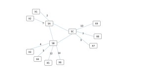
WIth the above example the following forwarding rows will exist on the three switches:

| Rule                  | SA Portset | SB Portset      | SC Portset |
| Unicast to X1         | 2          | SA              | SA         |
| Unicast to X3         | 7          | SA              | SA         |
| Unicast to X3         | SB         | 4               | SB         |
| Unicast to X4         | SB         | 5               | SB         |
| Unicast to X5         | SB         | 12              | SB         |
| Unicast to X6         | SB         | 14              | SB         |
| Unicast to X7         | SC         | SC              | 3          |
| Unicast to X8         | SC         | SC              | 7          |
] Unicast to X9         | SC         | SC              | 10         |
| Multicast to X1-X9    | 2,7,SB,SC  | SA,4,9,11,14,SC | SA,SB,7,10 |
| Multicast to X1,X4,X8 | 2, SB, SC  | SA, 5, SC       | SA, SB, 7  |

The last row (Multicast to X1, X4 and X8) can be formed from data each switch already has, each applying the same instruction to that data.

That’s it. Just execute that instruction on each switch and the subset multicast group will be created. It doesn’t even have to be acknowledge, after all the UDP datagrams are not being individually acknowledged either. The switch set up and the follow-on rendezvous transfer will be confirmed by the cryptographic hash of the delivered payload. It either matches or it does not.

I have submitted an IETF draft: https://tools.ietf.org/html/draft-bestler-transactional-multicast-00, but there hasn’t been much reaction.

This is a very minimal enhancement to IGMP/MLD snooping.

  • There is no change to the underlying L2 forwarding tables required. The same forwarding entries are being created, just with simpler transactions. This is an important constraint. If we could modify the firmware that actually forwards each packet we could just specify a “Threecast” IP header that listed 3 destination IP addresses. But there is no way that will ever happen, we need to deal with switch chips as they are.
  • There is no additional state that the switches must maintain, in fact there is less tracking required for a transactional subset multicast group than for a conventional multicast group.

The lack of response presents a challenge. The people who understood multicast did not understand storage, and most of the people who understood storage did not understand multicast.

We could do switch model specific code to shove the correct L2 forwarding rules to any given switch model, but that was not much of a long term solution. The required IGMP/MLD snooping required for this technique can be implmented in OpenFlow, but the number of switches that allow OpenFlow to modify any flow is extermely limited, effectively reducing it to being a “switch specific” solution.

OpenFlow does have the benefit of being constrained. Other local interfaces are not only model specific, they are unconstrained. In order to be able to do anything you effectively have to be given permission to do everything. In order for the network administrator to enable us to set those tables they would have to trust our application with the keys to their kingdom.

As a general rule I hate asking the customer network administrator to do something that I would fire my network administrator for agreeing to.

The Push model solves that because it only sets up multicast groups that are subsets of conventionally configured (and validated) groups, and only for the duration of a short transaction.

We came up with an alternate solution that involves enumerating the possible Rendezvous Groups sufficiently before they are needed that the latency of IGMP/MLD joins is not an issue. The transaction processing then claims that group in real-time rather than configuring it. I’ll describe that more in the next blog. For the balance of this blog I’d like to re-iterate exactly why push multicasting makes sense, and is very simple to implement.

It is also totally consistent with existing IGMP/MLD. It is really just a specialized extension of IGMP/MLD snooping.

To understand why this is benign you need to consider the following issues:

  • How is the group identified?
  • What are the endpoints that receive the messages?
  • What is the duration of the group?
  • Who are the potential members of the group?
  • How much latency does the application tolerate?
  • Are there any Security Considerations

Question 1: How is the Group Identified?

In IGMP/MLD listeners identify themselves. It is pull-based control of membership. The sender does not control or even know the recipients. This matches the multicast streaming use-case very well.

However it does not match a cluster that needs to distribute a transactional message to a subset of a known cluster. One example of the need to distribute a transactional message to a subset of a known cluster is replication within an object cluster. A set of targets has been selected through an higher layer protocol.

IGMP-style setup here adds excessive latency to the process. The targets must be informed of their selection, they must execute IGMP joins and confirm their joining to the source before the multicast delivery can begin. Only replication of large storage assets can tolerate this setup penalty. A distributed computation may similarly have data that is relevant to a specific set of recipients within the cluster. Having to replicate the transfer over multiple unicast connections is undesirable, as is having to incur the latency of IGMP setup.

Two solutions will be proposed where a sender can form or select a multicast group to match a set of targets, without requiring any extra interaction with THOSE targets as long as the targets are already members of a pre-existing multicast group. Allowing a sender to multicast to any set of IP addresses would clearly be unacceptable for both security and network administration reasons.

Question 2: What are the endpoints that receive the messages?

For the specific storage protocol we were working on the desired endpoints are virtual drives, not IP endpoints.

A given storage server can determine which of its virtual drives is being addressed solely from the destination multicast IP address. One of the questions we are seeking feedback on is whether this is unique to this storage protocol, or whether the ability to identify a multicast group as a set of higher layer objects is generally desirable.

Question 3: What is the duration of the group?

IGMP/MLD is designed primarily for the multicast streaming use-case. A group has an indefinite lifespan, and members come and go at any time during this lifespan, which might be measured in minutes, hours or days.

Transactional multicasting seeks to identify a multicast group for the duration of sending a set of multicast datagrams related to a specific transaction. Recipients either receive the entire set of datagrams or they do not. Multicast streaming typically is transmitting error tolerant content, such as MPEG encoded material. Transaction multicasting will typically transmit data with some form of validating signature that allows each recipient to confirm full reception of the transaction.

This obviously needs to be combined with applicable congestion control strategies being deployed by the upper layer protocols. The Nexenta Replicast protocol only does bulk transfers against reserved bandwidth, but there are probably as many solutions for this problem as there are applications. The important distinction here is that there is no need to dynamically adjust multicast forwarding tables during the lifespan of a transaction, while IGMP and MLD are designed to allow the addition and deletion of members while a multicast group is in use. The limited duration of a transactional multicast group implies that there is no need for the multicast forwarding element to rebuild its forwarding tables after it restarts. Any transaction in progress will have failed, and been retried by the higher-layer protocol. Merely limiting the rate at which it fails and restarts is all that is required of each forwarding element.

Question 4: Who are the members of the group?

IGMP/MLD is designed to allow any number of recipients to join or leave a group at will. Transactional multicast requires that the group be identified as a small subset of a pre-existing multicast group. Building forwarding rules that are a subset of forwarding rules for an existing multicast group can done substantially faster than creating forwarding rules to arbitrary and potentially previously unknown destinations.

Question 5: How much latency does the application tolerate?

While no application likes latency, multicast streaming is very tolerant of setup latency. If the end application is viewing or listening to media, how many msecs are required to subscribe to the group will not have a noticeable impact to the end user.

For transactions in a cluster, however, every msec is delaying forward progress. The time it takes to do an IGMP join is simply an intolerable addition to the latency of storing an object. This is especially so in an object cluster using SSD or other fast storage technology. The IGMP/MLD Join might take longer than the actual writing of storage.

Question 6: Are there any Security Considerations

Multicast Groups configured by this method are constrained to be a subset of a conventionally configured multicast group. No datagram can reach any destination that it cannot already reach by sending the datagram to referenced group.

Obviously the application layer has to know the meaning of packets sent on each multicast group, but that is already true of existing multicast UDP.

Proposed Method:

Set the multicast forwarding rules for pre-existing multicast forwarding address X to be the subset of the forwarding rules for existing group Y required to reach a specified member list.

This is done by communicating the same instruction (above) to each multicast forwarding network element.

This can be done by unicast addressing with each of them, or by multicasting the instructions. Each multicast forwarder will set its multicast forwarding port set to be the union of the unicast forwarding it has for the listed members, but result must be a subset of the forwarding ports for the parent group.

For example, consider an instruction is to create a transaction multicast group I which is a subset of multicast group J to reach addresses A,B and C. Addresses A and B are attached to multicast forwarder X, while C is attached to multicast forwarder Y. On forwarder X the forwarding rule for new group I contains: The forwarding port for A. The forwarding port for B. The forwarding port to forwarder Y (a hub link). This eventually leads to C. While on forwarder Y the forwarding rule for the new group I will contain: The forwarding port for forwarder X (a hub link). This eventually leads to A and B. The forwarding port for C.

Many ethernet switches already support command line and/or SNMP methods of setting these multicast forwarding rules, but it is challenging for an application to reliably apply the same changes using multiple vendor specific methods. Having a standardized method of pushing the membership of a multicast group from the sender would be desirable.

The Alternate Method:

But having a product depend upon a feature you are trying to get adopted doesn’t work so well. We needed a method of dynamically selecting Rendezvous Groups that was compatible with terrible IGMP/MLD Join latencies. I’ll explain that in the next blog.

Hyperconvergence: the Litmus Test

What’s in the name

It is difficult to say when exactly the “hyper” prefix was the first time attached to “converged” infrastructure. Hyper-convergence, also known as hyperconvergence, ultimately means a fairly simple thing: running user VMs on virtualized and clustered storage appliances. The latter in turn collaborate behind the scenes to a) pool combined local storage resources to further b) share the resulting storage pool between all (or some) VMs and c) scale-out the VM’s generated workload.

That’s the definition, with an emphasis on storage. A bit of a mouthful but ultimately simple if one just pays attention to a) and b) and c) above. Players in the space include Nutanix, SimpliVity and a few other companies on one hand, and VMware on another.

Virtualized storage appliance that does storage pooling, sharing and scaling is a piece of software, often dubbed “storage controller” that is often (but not always) packaged as a separate VM on each clustered hypervisor. Inquisitive reader will note that, unlike Nutanix et al, VMware’s VSAN is part and parcel of the ESXi’s own operating system, an observation that only reinforces the point or rather the question, which is:

True Scale-Out

True scale-out always has been and will likely remain the top challenge. What’s a “true scale-out” – as opposed to limited scale-out or apparent scale-out? Well, true scale-out is the capability to scale close to linearly under all workloads. In other words, it’s the unconditional capability to scale: add new node to an existing cluster of N nodes, and you are supposed to run approximately (N + 1)/N faster. Workloads must not even be mentioned with respect to the scale-out capabilities, and if they are, there must be no fine print..

Needless to say, developers myself including will use every trick in the book and beyond, to first and foremost optimize workloads that represent (at the time of development) one or two or a few major use cases. Many of those tricks and techniques are known for decades and generally relate to the art (or rather, the craft) of building distributed storage systems.

(Note: speaking of distributed storage systems, a big and out-of-scope topic in and of itself, I will cover some of the aspects in presentation for the upcoming SNIA SDC 2015 and will post the link here, with maybe some excerpts as well)

But there’s one point, one difference that places hyperconverged clusters apart from the distributed storage legacy: locality of the clients. With advent of hyperconverged solutions and products the term local acquired a whole new dimension, simply due to the fact that those VMs that generate user traffic – each and every one of them runs locally as far as (almost) exactly 1/Nth of the storage resources.

Conceptually in that sense, clustered volatile and persistent memories are stacked as follows, with the top tier represented by local hypervisor’s RAM and the lowest tier – remote hard drives.

hyperconverged

(Note: within local-rack vs. inter-rack tiering, as well as, for instance, utilizing remote RAM to store copies or stripes of hot data, and a few other possible tiering designations are intentionally simplified out as sophisticated and not very typical today)

Adding a new node to hyperconverged cluster and placing a new bunch of VMs on it may appear to scale if much of the new I/O traffic remains local to this new node, utilizing its new RAM, its new drives and its new CPUs. De-staging (the picture above) would typically/optimally translate as gradual propagation of copies of aggregated and compressed fairly large in size logical blocks across conceptual layers, with neighboring node’s SSDs utilized first..

But then again, we’d be talking about an apparent and limited scale-out that performs marginally better but costs inevitably much more, CapEx and OpEx wise, than any run-of-the-mill virtual cluster.

Local Squared

Great number, likely a substantial majority of existing apps keep using legacy non-clustered filesystems and databases that utilize non-shared LUNs. When deploying those apps inside VMs, system administrators simply provision one, two, several vdisks/vmdks for exclusive (read: local, non-shared) usage by the VM itself.

Here again the aforementioned aspect of hyperconvergent locality comes out in force: a vendor will make double sure to keep at least caching and write-logging “parts” of those vdisks very local to the hypervisor that runs the corresponding VM. Rest assured, best of the vendors will apply the same “local-first” policy to the clustered metadata as well..

Scenarios: probabilistic, administrative and cumulative

The idea therefore is to come up with workloads that break (the indeed, highly motivated) locality of generated I/Os by forcing local hypervisor to write (to) and read from remote nodes. And not in a deferred way but inline, as part of the actual (application I/O persistent storage) datapath with client that issued the I/Os waiting for completions on the other side of the I/O pipeline..

An immediate methodological question would be: Why? Why do we need do run some abstracted workload that may in no way be similar to one produced by the intended apps? There are at least 3 answers to this one that I’ll denote as, say, probabilistic, administrative and cumulative.

Real-life workloads are probabilistic in nature: the resulting throughput, latencies and IOPS are distributed around their respective averages in complex ways which, outside pristine lab environments, is very difficult to extrapolate with bell curves. Most of the time a said workload may actively be utilizing a rather small percentage of total clustered capacity (the term for this is “working set” – a portion of total data accessed by the app at any given time). Most of the time – but not all the time: one typical issue for users and administrators is that a variety of out-of-bounds situations requires many hours, days or even weeks of continuous operation to present itself. Other examples include bursts of writes or reads (or both) that are two or more times longer than a typical burst, etc.

Administrative maintenance operations do further exacerbate. For example, deletion of older VM images that must happen from time to time on any virtualized infrastructure – when this seemingly innocuous procedure is carried out concurrently with user traffic, long-time cold data and metadata sprawled across the entire cluster suddenly comes into play – in force.

Cumulative-type complications further include fragmentation of logical and physical storage spaces that is inevitable after multiple delete and rewrite operations (of the user data, snapshots, and user VMs), as well as gradual accumulation of sector errors. This in turn will gradually increase ratios of one or two or may be both of the otherwise unlikely scenarios: random access when reading and writing sequential data, and read-modify-writes of the metadata responsible to track the fragmented “holes”.

Related to the above would be the compression+rewrite scenario: compression of aggregated sequentially written logical blocks whereby the application updates, possibly sequentially as well, its (application-level) smaller-size blocks thus forcing storage subsystem to read-modify-write (or more exactly, read-decompress-modify-compress and finally write) yet again.

Critical Litmus Test: 3 simple guidelines

The question therefore is, how to quickly exercise the most critical parts of the storage subsystem for true scale-out capability. Long and short of it boils down to the following simple rules:

1. Block size

The block size must be small, preferably 4K or 8K. The cluster that scales under application-generated small blocks will likely scale under medium (32K to 64K, some say 128K) and large blocks (1M and beyond) as well. On the other hand, a failure to scale under small blocks will likely manifest future problems in handling some or all of the scenarios mentioned above (and some that are not mentioned as well).

On the third hand, a demonstrated scale-out capability to operate on medium and large blocks does not reflect on the chances to handle tougher scenarios – in fact, there’d be no correlation whatsoever.

2. Working set

The working set must be set to at least 60% of the total clustered capacity, and at least 5 times greater than RAM of any given node. That is, the MAX(60% of total, 5x RAM).

Reason for this is that it is important to exercise the cluster under workloads that explicitly prevent “localizations” of their respective working sets.

3. I/O profile

Finally, random asynchronous I/Os with 100%, 80/20% and 50/50% of write/read ratios respectively, carrying pseudo-random payload that is either not compressible at all or compressible at or below 1.6 ratio.

That’ll do it, in combination with vdbench or any other popular micro-benchmark capable to generate pedal-to-the-metal type load that follows these 3 simple rules. Make sure not to bottleneck on CPUs and/or network links of course, and run it for at least couple hours on at least two clustered sizes, one representing a scaled-out version of the other..

Final Remarks

Stating maybe the obvious now – when benchmarking, it is important to compare apples-to-apples: same vendor, same hardware, same software, same workload scaled out proportionally – two different clustered sizes, e.g. 3 nodes and 6 nodes, for starters.

The simple fact that a given hyperconverged hardware utilizes latest-greatest SSDs may contribute to the performance that will look very good, in isolation. In comparison and under stress (above) – maybe not so much.

One way to view the current crop of hyperconverged products: a fusion of distributed storage, on one hand and hybrid/tiered storage, on another. This “fusion” is always custom, often ingenious, with tiering hidden inside to help deliver performance and assist (put it this way) scaling out..

HyperConverged Storage Directions — How to get users down the path

I wanted to title this Hypo Diverged Storage, as seemingly there are many ideas of what “hyper converged” storage and architectures are in the industry. Targeted at developers and solution providers alike, this piece will strive to combine a string of ideas of where I think we want to go with our solutions, and I hope to dispel some arguments that are assumptive or techno-religious in nature. Namely
  • What is really necessary for a strong foundational technology/product
  • Emulate the service architectures
  • It just needs to be good enough
  • Containers: Just build out the minimum and rely of VMs/hypervisors to handle the rest
  • You must build fresh cloud native, immutable applications only
In my role at Stanford Electrical Engineering I have numerous interactions with researchers and vendors, including research projects that have now become the formative infrastructure companies in the industry. My hand in many of these has been slight, but we have had more effect in guiding the build out of usable solutions, taking many into production use first at our facilities. Among the many projects over time, we have dealt with the beginnings and maturation of virtualization in compute, storage, and networking. Today’s emerging on-prem and cloud infrastructure now takes as a given that we need to have all three. Lets target the assumptions.
1) To build out a production quality solution that works well in the ecosystem, you just need to make a killer (storage/compute/network) appliance or product.
In many discussions, people may notice a mantra that most companies rightfully focus on building technology from a position of strength such as storage or networking, but miss out when they only attempt to integrate with one of the other legs of the virtualization stool. They rush to market but fail to execute well or deliver what end users actually want because the integration is half baked at most. I’ve worked with great storage products that focus on network access alone, but can’t deal with bare-metal container hypervisors; SDN products that can help make OpenStack work well for tenants, but ignore the storage component that itself is on the network; Storage products that require dedicated use of network interfaces for I/O without awareness of virtualized interfaces; Hypervisors that use networks for storage but can’t themselves hide transient network failure from the guests they host. These are just samples but they inform us that its hard to get it all right.
Although its a lot for any going concern to address, it is necessary for products and solutions to have well thought out scale-up and scale-out approaches that address all three legs of the stool. One could argue the forth leg could be orchestration, and that might need to be taken into account as well. Regardless, a focus on providing an integrated storage/networking/virtualization solution in the more simple cases, and building from there is more advantageous to customers looking to grow with these solutions long term.
2) To build a successful hyper converged product, you need to emulate how Google/AWS/etc build out their cloud infrastructure. 
I’d argue that most potential customers won’t necessarily want to pick a random vendor to bring AWS-like infrastructure on site. The economics and operational complexity would likely sway them to just host their products on AWS or similar, regardless of how much performance is lost in the multiple layered services offered by Amazon. In most cases, mid-enterprise and higher customers already have various solutions adopted, thus necessitating a brown field approach to adopting hyper converged solutions.
This gets to one important belief I have. The idea is that regardless of your solution, the ability for a site to bootstrap its use with minimal initial nodes (1 or more), truly enable migration of work loads onto it, and with time and confidence, allow the customer to grow out their installation. This pushes out another assumption that the hardware is uniform. With gradual roll outs, you should expect variation in the hardware as a site goes from proof-of-concept, to initial roll out and finally full deployment. All the while, management of the solution should allow the use of existing networks where possible and the phase out of or upgrade of nodes over time. There is no “end of deployment” as it is more of a continuous journey between site and solutions vendor.
You’ll notice a theme, that bootstrapping of initial storage and networking, and simply, is more important than to emulate the full stack from the get go. Don’t try and be Amazon, just make sure you have strong foundation storage/compute/networking so that you can span across multiple installations and even over pre-existing solutions like Amazon.
3) Just get the product in the door with good initial bootstrapping.
Extending from the above, simply bootstrapping is not enough. Support of a product tends to kill many startups or seasoned companies. However, it really bedevils startups as they strive to get initial market acceptance for their investors. In the end, a hyper converged solution is a strong relationship between vendor(s) and the customer. Deployment should be considered continuous up front, so the ability to add, maintain, and upgrade a product is not only central to the relationship, it informs the product design. Consider what hyper converged truly means. Each node it self sufficient but any work load should be able to migrate to another node, and a loss of any given node should not overly strain the availability of the infrastructure.
I don’t want to take away too much from how one should focus on ease of initial deployment. That can win customers over. However, keeping users of converged infrastructure happy with the relationship requires happiness with the overall architecture and not the initial technology.
4) Containers can run well enough in virtual machines. Just build on top of VMs and then layer on top our storage and network integrations.
VMs alone are no longer the target deployment, but rather applications and/or app containers. In the rush to enable container deployment, vendors take the shortcut and build on top of existing VM infrastructure. Its worse when it comes to existing hyperconverged solutions that have heavy infrastructure requirements to support VMs. If one now sees lightweight containers as a target, ones assumptions on what makes hyperconverged infrastructure changes. Merely adopting existing mature VM infrastructure becomes is its own issue.
I love the work that Joyent has done in this space. They’ve argued well, using mature container technology not found in Linux, and brought Linux and Docker into their infrastructure. What makes them better than the present competition is that they run their containers on bare-metal and right on top of virtualized storage (ZFS backed) and maturing network virtualization. The solution presented works wonders for those operating the tech as an IAAS. Market acceptance of a non-native Linux solution or some of the present non-clustered FS components may limit the appeal of excellent technology. At the same time, the primary market as a public cloud places them in the shadow of the larger players there.
A Joyent-like technological approach married with full SDN integration could be the dream product, if made into such a product. Already, the tech proves the assumption of using VMs to be a weak proposition. What VM infrastructure has and containers need for wider adoption is SDNs, namely overlay networks. If we enable not only pooled storage but pooled networking, we can gain better utilization of the network stack, inherent path redundancy, and via an SDN overlay, a safe way to build tenant storage networks arbitrarily over multiple physical networks, perhaps across multiple vendor data centers. Think how this serves the customers potential container mobility.
5) Docker is containers / Containers need to be immutable by design for a scale out architecture
All the above leads to this point. Taking past experience and intuition, I think that what holds back adoption of next generation infrastructure throughout the industry is in fact the religious arguments around immutability. The work loads that could make use of better solutions coming to market require some level of persistence per node/container. Though live migration may not be warranted in many cases, the ability to upgrade a container, vertically scale it, or run “legacy” applications using these new operation approaches will be required of a mature container solution. We just haven’t gotten there yet. A scale-out infrastructure can allow for persistent type containers, as long as end users architect for the expected failure modes that may occur for this application profile.
What matters to customers is the ability to use the build out and scale out nature of the cloud, with known data and operational redundancy and recovery at its core. In many cases, work loads that the market presents may not yet fit into the Docker world, but they can definitely be containerized and virtualized to hyper converged storage solutions.
If you believe that these are the target users, who don’t necessarily need to develop the whole solution with a ground-up “cloud” architecture, don’t wish to run on the public cloud in all cases, and need a way to on-board cloud technology into the present organization in a progressive way, you will see where we all collectively need to go. Its not so much a hyper converged world, but an inviting, enabling solution space that starts simple (perhaps one compute+storage node), scales out non-uniformly using SDNs to tie in the nodes as they come and go. Customers can adopt small, and grow with you as you build out better, more complete infrastructure.
Forward thoughts:
My experience shows that the IT work place is changing, and those managing data centers need to adjust to adopt the skill sets of cloud operators. There is pressure I’ve seen in many organizations to convert both the business and the work force to adopt cloud technology. The opposing forces are institutional resistance (or requirements) to not adopt the public cloud, or critical work loads that can’t trivially be converted to Docker-style immutable containers. That is a present market condition needing solutions. A stand alone product won’t work, but a long term approach the grows with an organization through this IT landscape change will serve both customers and solution providers well.

CrowdSharing Part 2

When it comes to ad-hoc wireless (mesh) networks, we probably visualize something like this:

SPAN

The picture is a youtube screen grab; the video itself introduces the project SPAN (github: https://github.com/ProjectSPAN) to “enable communications in challenged environments”. Wikipedia has a somewhat better picture though, covering all kinds of wireless scenarios, including satellite.

Introduction

Wireless ad hoc networks go back 40 plus years, to the early 1970s (DARPA) projects, with the 3rd generation taking place in the mid-1990s with advent of 802.11 standards and 802.11 cards – as always, wikipedia compiles a good overview 1 2 3.

Clearly there’s a tremendous and yet untapped value in using cumulative growing power of smartphones to resolve complex tasks. There are daunting challenges as well: some common (security, battery life and limited capacity, to name a few), others – application specific. Separate grand puzzle is to monetizing it, making it work for users and future investors.

There’s one not very obvious thing that has happened though fairly recently, as far as this 40 plus year track. Today we know exactly how to build a scaleable distributed object storage system, system that can be deployed on pretty much anything, would be devoid of the infamous single-MDS bottleneck, load-balance on the backend, and always retain the 3 golden copies of each chunk of each object. Abstractions and underlying principles of this development can in fact be used for the ad hoc wireless applications.

I’ll repeat. Abstractions and principles that at the foundation of infinitely scaleable object storage system can be used for selected ad hoc wireless applications.

Three Basic Requirements

CrowdSharing (as in: crowdsourcing + file-sharing) is one distinct application (the “app”), one of several that can be figured out today.

The idea was discussed in our earlier blog and is a very narrow case of an ad hoc network. CrowdSharing boils down to uploading and downloading files and objects (henceforth “fobjects” 4, for shortness sake) whereby a neighbor’s smartphone may serve as an intermediate hop.

(On the picture above, Bob at the bottom left may be sending or receiving his fobject to Alice at the top left 5)

CrowdSharing by definition is performed on a best-effort basis, securely and optimally while at the same time preventing exponential flooding (step 1: Bob (fobject a) => Alice; step 2: Alice (fobject a, fobject b) => Bob; step 3: repeat), where the delays and jitters can count in minutes and even hours.

Generally, 3 basic things are required for any future ad hoc wireless app:

  1. must be ok with the ultimate connectionless nature of the transport protocol
  2. must manipulate fobjects [^4]
  3. must be supported by a (TBD) business model and infrastructure capable to provide enough incentives to both smartphone users and investors

Next 3 sections briefly expand on these points.

Connectionless

There’s a spectrum. On one side of it there are transport protocols that, prior to sending first byte of data, provision resources and state across every L2/L3 hop between two endpoints; the state is then being maintained throughout the lifetime of the corresponding flow aka connection. On the opposite side, messages just start flying without as little as a handshake.

Apps that will deploy (and sell) over ad hoc wireless must be totally happy with this other side: connectionless transports. Messages may take arbitrary routes which also implies that each message must be self-sufficient as far as its destination endpoint and the part of the resulting fobject it is encoding. Out-of-order or duplicated delivery must be treated not as an exception but as a typical sequence of events, a normal occurrence.

Eventually Consistent Fobjects

Fobjects 4 are everywhere. Photos and videos, .doc and .pdf files, Docker images and Ubuntu ISOs, log structured transaction logs and pieces of the log files that are fed into MapReduce analytics engines – these are all immutable fobjects.

What makes them look very different is an application-level, and in part, transactional semantics: ZFS snapshot would be an immediately consistent fobject, while, for instance, a video that you store on Amazon S3 only eventually consistent..

Ad hoc wireless requires eventual consistency 6 for the application-specific fobjects.

Business Model

On one hand, there are people that will pay for the best shot to deliver the data, especially in the situations when/where the service via a given service provider is patchy or erratic at best, if present at all.

On another, there is a growing smartphone power in the hands of people who would like to maybe make an extra buck by not necessarily becoming an Uber driver.

Hence, supply and demand forces that can start interacting via CrowdSharing application “channel”, thus giving rise to the new and not yet developed market space..

How that can work

Messages

On the left side of the diagram below there’s a fobject that Bob is about to upload. The fobject gets divided into chunks, with each chunk getting possibly sliced as well via Reed-Solomon or its derivatives. RSA (at least) 1024-bit key is used to encrypt those parts that are showed below in red and brown.

Bob-and-Alice

Each chunk or slice forms a self-sufficient message that can find its way into the destination object through unpredictable and not very reliable set of relays, including in this case Alice’s smartphone. Content of this message carries metadata and data, a simplified version of this is depicted above. Destination (network) address is the only part that is in plain text, Bob’s address, however, is encrypted with a key known to the service provider at the destination, while the content itself may be encrypted with the different key that the provider does not have.

The entire message is then associated with its sha512 content digest that simultaneously serves as a checksum and a global (and globally unique) de-duplicator.

Actors

The diagram shows 3 “actors”: Bob – uploads his fobject; Alice – provides her smartphone’s resources and maybe her own home network (or other network) to forward Bob’s object to the specified destination.

And finally, Application Provider aka Control Center.

The latter can be made optional; it can and must serve though to perform a number of key functions:

  • maintain user profiles and their (user) ratings based on the typical like/dislike and trust/distrust feedback provided by the users themselves
  • record the start/end, properties and GPS coordinates of each transaction – the latter can become yet another powerful tool to establish end-to-end security and authenticity (and maybe I will talk about it in the next blog)
  • take actual active part during the transaction itself, as indicated on the diagram and explained below, and in particular:
  • act as a trusted intermediary to charge user accounts on one hand, and deposit service payments to users that volunteer to provide their smartphones for CrowdSharing service, on another..

Steps

Prior to sending the first message, Bob’s smartphone, or rather the CrowdSharing agent that runs on it, would ask Alice’s counterpart whether it is OK to send. Parameters are provided, including the sha512 key-digest of the message, and the message’s size.

At this point Alice generally has 3 choices depicted above atop of the light-green background. She can flat-out say No, with possible reasons including administrative policy (“don’t trust Bob”), duplicated message (“already has or already has seen this sha512”), and others.

Alice can also simply say Yes, and then simply expect the transfer.

Or, she can try to charge Bob for the transaction, based on the criteria that takes into account:

  • the current CrowdSharing market rate at a given GPS location (here again centralized Application Provider could be instrumental)
  • remaining capacity and battery life (the latter – unless the phone is plugged-in)
  • Alice’s data plan and its per month set limits with wireless service provider, and more.

Bob, or rather the CrowdSharing agent on his smartphone will then review the Alice’s bid and make the corresponding decision, either automatically or after interacting with Bob himself.

Payments

Payments must be postponed until the time when Alice (in the scenario above) actually pushes the message onto a wired network.

Payments must be likely carried out in points (and I suggest that each registered user deposits, say $20 for 2,000 CrowdSharing points) rather than dollars, to be computed and balanced later based on the automated review of the transaction logs by the Application Provider. Accumulated points of course must convert back into dollars on user’s request.

The challenges are impressive

The challenges, again, are impressive and numerous; there’s nothing though that I think technically is above and beyond today’s (as they say) art.

To name a few.. Downloading (getting) fobjects represent a different scenario due to the inherent asymmetry of the (Wi-Fi user, wired network) situation. BitTorrent (the first transport that comes to mind for possible reuse and adaptation) will dynamically throttle based on the amount of storage and bandwidth that each “peer” provides but is of course unaware of the consuming power and bandwidth of the mobile devices on-battery.

Extensive control path logic will have to be likely done totally from scratch – the logic that must take into account user-configurable administrative policies (e.g., do not CrowdShare if the device is currently running on-battery), the limits set by the wireless data plans 7, the ratings (see above), and more.

Aspects of the business model are in this case even more curious than technical questions.


  1. Wireless ad hoc network 
  2.  Stochastic geometry models of wireless networks 
  3.  Wireless mesh network 
  4. fobjects are files and/or objects that get created only once, retrieved multiple times, and never updated. Not to be confused with fobject as a combo of “fun and object” (urban dictionary) 
  5. Alice and Bob 
  6.  Eventual consistency 
  7. In one “overage” scenario, Alice could “charge” Bob two times her own overage charges if the latter is getting reached or approximated (diagram above) 

Map-free Multi-site Replication

A distributed storage system has do a great job of replicating content. Building a highly available storage service out of mildly reliable storage devices requires replicating after each failure. Replication is not an exception, it is a continuous process. So it’s important.

The design of the CCOW (Cloud Copy-on-Write) object storage system deals with replication within a local network very well. What it does not deal with anywhere near as well is spreading content over very long round-trip-times, as in different sites. I needed a feature that would allow customers to federate multiple sites without requiring 40 Gbe links connecting the sites.

This is not specific to CCOW object storage. The need to provide efficient storage locally will force any design to partition between “local” updating, which is fairly fast, and “remote” updating which will be considerably slower. If you don’t recognize this difference you’ll end up with a design that does all updates slowly.

But I needed a solution for CCOW. My first thought on how to replicate content between federated sites was to just layer on top of software bridges.

The problem actually maps fairly well:

  • Each site can be thought of as a switch.
  • The “switch” can deliver frames (chunks) to local destinations, or to links to other switches (sites).
  • A frame (chunk) is never echoed to the same link that it arrived upon.
  • There is no need to provision a site topology, the Spanning Tree will discover it. The latter spanning tree algorithms will do it better.

If you are not familiar with the Spanning Tree algorithms I suggest you go read up on them. Spanning Tree made Ethernet networking possible. See https://en.wikipedia.org/wiki/Spanning_Tree_Protocol.

Basically, we start with a set of linked Sites:

MultiSite1

Spanning Tree algorithms effectively prevent loops by logically de-activating some of the links.

MultiSite2

So re-using existing software (software switches and existing long-haul tunnels) was a very tempting solution, especially since it directly re-used networking layer code to solve storage layer problems. Pontificating that networking solutions are applicable to storage is one thing, actually leveraging network layer code would prove it.

This leads to the following distribution pattern, in this example for a frame originating from Site V.

MultiSite3

But it turns out that the storage layer problem is fundamentally simpler.

Radia Perlman’s spanning tree prevnts loops by discovering the links between the switches, and without central decision making de-activates a subset of the links so that would have enabled forwarding loops. It does this no matter how the switches are linked. It de-activates links to avoid loops. This is needed because Ethernet frames do not have a time-to-live marker. Without spanning tree it would be very easy for Switch A to forward a frame to Switch B, which would forward it to Switch C which would forward it to Switch A. While rare, such loops would crash any Ethernet network. Spanning tree was a simple algorithm that prevented that totally.

The fundamental assumption behind spanning tree was that links had to be de-activated because switches could not possibly remember what frames they had previously forwarded. Recognizing that a frame was being looped around would require remembering frames that have been forwarded eons previously, possibly even milliseconds.

If you understand how switches work the last thing any switch wants to do is to remember anything. Remembering things takes RAM, but more critically it takes time to update that RAM. RAM may get cheaper, but remembering things always takes longer than not remembering them and switches will kill to trim a microsecond from their relay time.

But remembering things is exactly what a storage cluster is deigned to do.

It turns out that the multi-site forwarding algorithm for multi-site storage of fingerprinted chunks is stunningly simple:

On receipt of a new Chunk X on one Inter-segment link:

If Chunk X is already known to this cluster

Do nothing.

Otherwise

Replicate Chunk X on all other inter-site inks.

Remember Chunk X locally.

That’s it. Having a cryptographic hash fingerprint of each chunk makes it easy to identify already seen chunks. This allows multiple sites to forward chunks over ad hoc links without having to build a site wide map, and all links can be utilized at all times.

Now the forwarding pattern is enhanced and there is no delay for building a tree:

Multisite4